Character Animation 101: Animation Mode and Motors
Welcome back to Learning 2D Character Animation 101! Our fourth lesson will focus on the procedural animation tools available when animating with Creature 2D.

Welcome back to Learning 2D Character Animation 101! Our fourth lesson will focus on the procedural animation tools available when animating with Creature 2D (read our third lesson on Weighting Your Character Rig here).
Now that your rig is complete, it’s time to animate your character. This tutorial will lay the groundwork for using physics motors and bone motors to bring your character to life—tools that make creating beautiful 2D animations much easier than simply using traditional keyframe animation. Once you complete this tutorial, you will be able to generate character motion and secondary motion with minimal effort, which will provide a foundation for creating animations and loops like walk cycles (to be covered in the next tutorial).
What is a Bone Motor?
Bone Motors can affect either a group of bones or individual bones. They procedurally generate motion on your bones using a variety of input parameters. Without them, you would have to manually position the placement and rotation of every single bone and joint. This would make the animation process very time consuming, especially for scenes attempting a photorealistic effect. There are other motor types within Creature, for this lesson we will cover the bone motors that directly impact your skeletal rig.
Several bone motors utilize two distinct methods to determine how the placement of a parent bone will affect the children underneath or vice versa. These two methods are known as FK (Forward Kinematics) and IK (Inverse Kinematics), which are used across 3D and 2D programs to create skeletal animation more efficiently. These terms originated from the field of robotics, but in this series we will focus on their application to animation.
Below you can see how different bone motors impact the speed of animating. The top chain of bones is manually positioned at each joint with an FK motor installed. The hierarchy of the bottom chain automatically reacts to the placement of the end bone with an IK motor applied.
The most basic form of manually animating your character is achieved with the FK bone motor, which is installed by default. FK (Forward Kinematics) is the process of moving connected limbs based on their parenting (if you completed the Adding Bones to Your Character Tutorial, you’re already an expert in how FK works). FK allows you to puppeteer and pose your character like you would an action figure.
IK, on the other hand, works in an almost opposite fashion. It allows the animator to set a target position for the end effector on a chain of bones. The IK bone motor will automatically calculate the orientation and position for the rest of the bones. This is why IK is often used for leg animation, where the motion is generated by following foot placement.
IK is also commonly used for instances where part of your character needs to be fixed to an object or part of the environment. For example, having your character holding on to something stationary such as a handle or handrail. The character’s hand should stay planted on the object similar to having a character’s foot planted on the ground, regardless of how the torso is moving around.

With bone motors you have the power to animate complex motions using only a few settings. This blog post will cover three topics related to bone and physics motors: 1) how to make sure your rig has the most efficient IK and FK motors installed for easy rig manipulation 2) how to add a natural physical bounce to your character and 3) how to add secondary motion to your character so that accessories, feathers, and hair behave differently as your character moves. Creature has many motors to choose from that can generate unique effects and simplify the process of creating high quality motion. Mastering these will allow you to focus on the details that make your animations stand out and go the extra mile.
Step-By-Step guide on how to use Bone Motors in Creature.
Step 1: Switch from Mesh/Rig mode to Animation Mode
Click on the large Mesh or Rig button on the upper left and select Animate.
Step 2: Install IK Motor
To install a bone motor first select the bone or group of bones from your character, such as the bones for the left leg. Under the Motors window, on the right side of the Creature interface, you will find the “Install Motor” button beneath the Bone Motors hierarchy. A window will pop up allowing you to select the Bone Motor to install. For the legs, let’s install the “IK Motor”.
The IK Motor requires more than one bone to be selected in order to work. As a result, you will be able to grab and pull on the end joint to pose your character like a puppet. Depending on the direction your character is facing you may need to go to the Motor Settings and change the “Valid IK Angle” from positive to negative.
Step 3: Install Bounce Motor
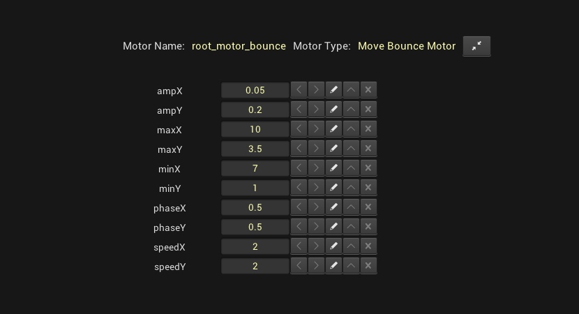
Select the Root Bone directly or from the Bones Tab under the Motors window on the right. Once selected click on Install Motor and select “Move Bounce Motor”. This will cause the selected bone to oscillate linearly around a specific point. Adding a Bounce Motor is important if you want to use other physics and force motors in Creature. The Bounce Motor generates motion for the additional motors to react to, enabling you to create secondary motions automatically. Change the settings for this motor by selecting the Root Bone and adjusting the numbers at the bottom of the Motors window.
First, lower the values for ampX and ampY. This will adjust how far your character will move in the X and Y axis of the bounce. Next, lower the number for speedY and speedX to slow down the movement for both the X and Y axis. You can preview the changes by either pressing Play at the top or having Animation Preview toggled on. You can toggle this window from the Animation tab on the top menu bar.
To keep the feet planted on the ground instead of bouncing along with the Root bone, you can install the Free FK Motor. This will keep the selected bone at a fixed position in world space according to your placement.
If you installed the wrong motor, select the bone and click “Remove Motor” button under the bone motors hierarchy. Two options will appear, choose the “Remove/Clear Animation from Selected Motor” option. This will revert the bone back to the default FK Motor.
Below are the values I used for Pluma, you can use similar values on your own bipedal character to get a more subtle bounce.
For Pluma’s legs I found that I got a smoother and rounder deformation from the knees when I added an extra joint. These are sometimes referred to as helper joints, and they are used to aid in the visual deformation of a mesh. In this situation, I wanted to avoid the sharper pinch from having a single joint. You can add additional joints when you also want to soften rotation between two limbs.

Step 4: Install Bend Physics Motors
Now that your character has some movement we can start installing motors to areas heavily affected by physics such as hair, feathers, and loose fabric. I recommend installing motors one at a time so you can make sense of the changes being made from adjusting the motor settings. Otherwise, it can be hard to troubleshoot unwanted movement or “explosions” that may be caused by the default values.

When pressing play to preview an animation, it is normal for the physics to take a few seconds to stabilize. In a later lesson, we will cover how to export specific parts of animation to cut out any artifacts during playback. If the physics do not stabilize then you will need to continue making adjustments to the installed motor settings or double check your skeletal hierarchy and weighting.

Select a chain of joints that will share the same motor. If there are a lot of bones, it will be easier to select them through the bone motors hierarchy. Once selected, click the Install Motor button. Select Bend Physics Motor from the pop-up window. If you press play you will see the Bend Physics Motor react to the motion generated by your Bounce Motor.

Step 5: Adjust the Bend Physics Motor Settings
As you can see, Pluma’s ponytail is reacting too strongly to the Bend Physics Motor. We can adjust the motor by selecting any bone the motor has been applied to. After selecting a bone from Pluma’s ponytail, we can adjust the settings for the Bend Physics Motor from the bottom of the motors window. There are five settings you can use to refine the motor.

5.1: Damping, determines how quickly the system bleeds energy. Increasing this value will result in slower movement. If you decrease it too much however, the animation could explode and become unstable.

5.2: FadeStiffnessRatio, determines how to fade the energy away along the chain of bones. In most cases, the preset value should be sufficient.
5.3: GravityFactor, determines how much gravity is affecting the system. By entering a value of 0 you can have bones ignore the force of gravity. Increasing the gravity will result in objects appearing heavier.

5.4: Stiffness, determines how bendable the material is Damping and Stiffness affect each other, so it is good to modify these values together. In the example below you can see that in comparison to a damping value of 800, a stiffness of 50 is too low. This results in the ponytail moving very slowly. We get much better results when the stiffness is changed with a value that is closer or equal to the number we entered for damping. If we go to the opposite extreme and have the stiffness set much higher than the damping, the damping is not strong enough to stabilize the animation.

5.5: StretchStiffness, determines how stretchy the material is. For now, keep this value the same as stiffness. Once you’ve modified the motor settings to get more stable results you can begin to change the stretchStiffness and stiffness to match the physical properties of the mesh regions. For example, the chains on Pluma’s torso should be able to bend due to the many chain links, but should not stretch since it is made of metal. On the other hand, the loose bandage on Pluma’s arm should be able to bend and stretch since it is made of cloth.
The result of modifying these values are dependent on your skeletal hierarchy and weighting. It may take time to get a feel for what numbers to enter in order to get the desired results. Below you can see the set of values I found that worked well for my rig of Pluma’s ponytail, her bangs, the main tail feather, and the feather in her hair.

Step 6: Install Pin Rope Physics Motor
The Pin Rope Physics Motor is similar to the Bend Physics Motor but with the addition of the input fields pinX and pinY. This allows you to get the benefit of physics-driven motion but with a pinpoint to hold one end of the chain of joints. This is useful for animating ropes or chains that are tied or hooked from one end. Animating this with an IK or Free FK bone motor would keep one end of the joints in place but would miss out on the natural movement that results from having a bend physics or pin rope physics motor installed.

Start by selecting the group of bones and installing the Pin Rope Physics Motor. You will notice that the start of the chain of bones follows along with its parent in the skeletal hierarchy while the last joint attempts to stay in sync with the position entered in the pinX and pinY fields for the motor settings.

Step 7: Apply Bone Tracking
Only the left side of the chain is following along with Pluma’s torso while the right side attempts stay in place with the pinX and pinY coordinates. To get both ends of Pluma’s chain to follow along with her torso we will need to utilize a tracking bone. Go back into Rig mode and create bone in the location you want the chain to connect to. For Pluma, I parented this new bone to one along her spine to inherit the appropriate motion. Don’t worry about assigning mesh regions or weighting.

Switch back to Animate Mode and select the chain of bones currently sharing the Pin Rope Physics Motor. Click the Animate tab and select the “Apply Bone Tracking” option, a pop-up window will appear. Expand the “Bone to Track” drop down and select the tracking bone you just created in Rig Mode. You should see that your chain of bones now snaps to the tracking bone when you press play.

Now we can repeat the same steps for the chain on the bottom and adjust the motor settings to get the desired results. If you make adjustments that will change the animation of the tracking bone you will need to re-do the previous step to Re-Apply Bone Tracking from the Animation tab. One example would be modifying the Bounce Motor settings on the root bone.

Below are the settings I used for the chains’ Pin Rope Physics Motor. You can ignore the pinX and pinY and leave them at their default values. I made the damping and stiffness values different between the upper and lower chain so there could be an offset to avoid having them bounce in perfect unison.
If you want both motors to share the same values select a bone with the source motor values and click CTRL+SHIFT+D to copy. Then select a bone with the motor that will receive these values and click CTRL+SHIFT+A to paste. You can find these commands under the Animation tab as well.

Step 8: Adjust Rig for Better Physics
The more joints you have in a chain of bones, the more force is being applied across the whole region when adding physics. Using fewer bones with a physics driven motor is best for objects with little to no flexibility and will result in a much more subtle motion. Having more bones is great for objects such as hair, cloth, or rope where you want the motion to flow with a lot more energy. It is important to find the right balance, adding too many bones will make it difficult to control the physics from the motor settings and result in more explosions and sporadic movement.

In the below example with the two chains, reducing the number of joints for the upper chain made it much easier to adjust the settings on the installed Pin Rope Physics Motor and get the desired results. This example also demonstrates the result of applying a tracking bone on the left side (top chain) of a chain of bones vs the right side (bottom chain). You will notice that the force being applied to each chain is strongest on the side with the tracking bone.

To make changes to your skeletal hierarchy, switch back to Rig mode. Change from region mode to bone mode and make sure you are using the selection tool.

Select the parent bone you want to remove. Clicking the Delete this Bone button will get rid of it and all children parented underneath it. Now stretch out the remaining joints starting from the first parent bone. Next, switch to weighting mode and apply auto weighting on each joint.

Now when you switch back to Animation mode, the remaining bones should still share the same installed motor and adjust the animation to account for the change in your rig. The motor settings may need to be adjusted to account for fewer bones.

Step 9: Apply and Adjust All Motors
Now that we have gone over the basic motors, you can continue to install them on the applicable bones or groups of bones. With the Bounce Motor set up, you should be able to see exactly how your adjustments to the motor settings affect the animation. With a few clicks and simple value adjustments, you can have a lively character without manually creating a single keyframe of animation!
Toggle the bones on/off during playback from underneath the motor hierarchy list. Turning off the bones during playback will help when they are blocking your view of the mesh regions, especially when you need to check the weighting. It is also good practice to show the bones during playback to see how they react to any changes made within the bone motor settings.

Stay tuned for the next lesson on Animation mode. You’ll learn how to use the animation timeline, utilize keyframes, and create your first walk cycle!
Atlas of Creature Tools Used
Bone Motors
- FK Motor: Set the orientation of a bone manually.
- IK Motor: Pose bones to a target point.
- Move Bounce Motor: Oscillates bones in the x and y directions.
- Free FK Motor: Set the position of a bone manually, ignoring parent animation.
- Bend Physics Motor: Applies rope and bend physics to bones.
- Pin Rope Physics Motor: Applies rope and bend physics to bone with directable ends
Bone Motor Settings
- Damping: Determines how quickly the system bleeds energy. Increase this value if you have unstable results or want slower movement.
- FadeStiffnessRation: Determines how to fade the energy away along the chain of bones. In most cases, the preset value should be sufficient.
- GravityFactor: Determines how much gravity is affecting the system.
- Stiffness: Determines how bendable the material is. Every increase in stiffness should be accompanied by an increase in damping for stable results.
- StretchStiffness: Determines how stretchy the material is. Similar to stiffness, every increase in stretchStiffness should be accompanied by an increase in damping for stable results.
- Valid IK Angle: Determines which direction a group of bones will bend towards when installed with the IK Motor.
- ampX and ampY: Modifies the distance a bone will travel in the x or y axis.
- speedX and speedY: Adjusts the speed at which the bone will travel in the x or y axis.
- pinX and pinY: Determines a fixed point in World Space for the end of a chain of bones to aim for.
Animation Mode
- Animation tab: Located at the top left of Creature, contains a drop down list of additional Animation Mode options and tools.
- Play: Allows you to start and stop your animation.
- Animation Preview Window: Toggleable from the Animation tab, a small window to preview your animation changes live without pressing play.
- Motor Hierarchy: A list of bones and their associated Bone Motors.
- Install Motor: Allows you to change the Bone Motor associated with the currently selected bone(s).
- Remove Motor: Reverts the Bone Motor back to the default FK Motor for the select bone(s).
- Show bones on playback: A toggleable check box that allows you to show or hide the bones when you press play.
- Helper Joints: Additional joints added to help create smoother deformations.
- Tracker Bone: An extra bone created to track a certain position.
- Apply Bone Tracking: Accessible from the Animation tab, allows you to set the Tracker Bone that a group of bones with the Pin Rope Physics Motor installed will follow.
- Copy Motor Setting Values: Select bone(s) with source motor settings and click CTRL+SHIFT+D to copy.
- Paste Motor Setting Values: Select bone(s) that will receive the motor settings and click CTRL+SHIFT+A to paste.
Up Next
Stayed tuned for our next lesson on Animating a Walk Cycle in Creature!
Creature animation software free download is available here! Students of this tutorial can use the code DMCreature101 for a free 30 day license, redeemable here.