How to Build Your Own Box Robot in Unity
In this tutorial you’ll learn how to create your own self-walking, humanoid robot in Unity with DeepMotion Avatar.

In this tutorial you’ll learn how to create your own self-walking, humanoid robot in Unity with DeepMotion Avatar.
This blog will cover:
- How to create a 3D robot character out of Unity box colliders.
- How to add articulated physics to your box robot[1].
- How to make your character balance and walk on its own.
The DeepMotion Avatar SDK for Unity and Unreal can be downloaded through our portal and is free to try for new users, sign up here!
This tutorial was created using the 2018.02.13 build of Avatar, with the 2017.0.2f3 version of Unity.
Part 1: Building Your Box Robot
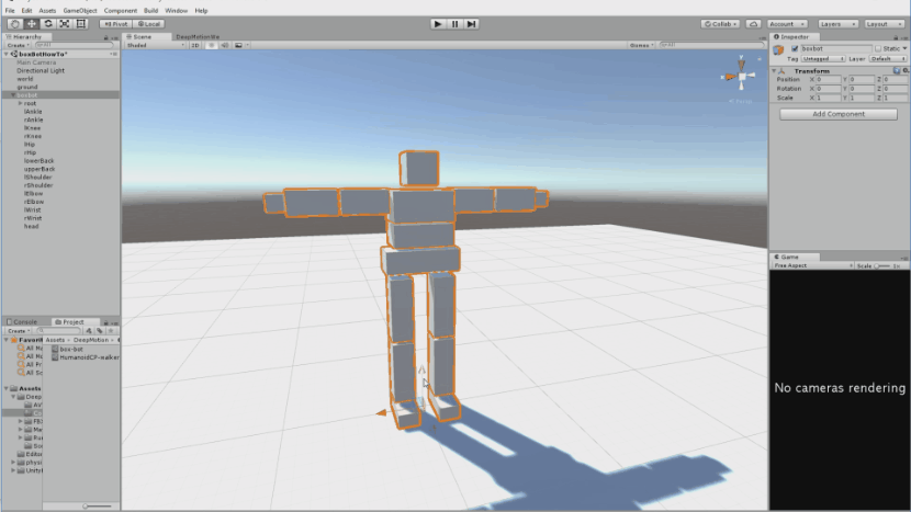
The humanoid robot we are making will stand roughly 2-3 units (meters) tall, and will be comprised of entirely Unity box colliders. When setting up your humanoid the articulation components will need to be inside a parent game object with no scaling (1, 1, 1). For the body parts, you can either follow the scale mentioned in the tutorial or use your own.
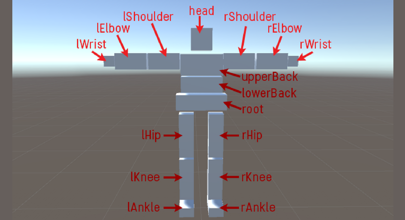
The box humanoid robot in the tutorial will have the following body parts:
- The legs are comprised of toes, feet, calves, and thighs.
- The arms for this bot will have a hand, forearm, and upper arm. If desired you can skip the elbow joint.
- The torso for this box bot will have 3 sections, starting from the root that connects the legs, and then the mid and upper back. If you want to add extra torso sections, you can.
- The head connected to the upper back.
When creating the body parts for your robot, you can either use the mesh at the same level of the colliders, or have the colliders as children and use your own mesh. More detail on colliders can be found here.
We’ll start with a scene containing the DeepMotion Avatar physics world and a ground plane with a physics material, and will go over creating the basic humanoid shape with the necessary tntLink components added to the body parts. Once we’ve created the entire body, we’ll go over how to set up the joints and how to make it walk.
Making Your Robot Body Parts
If you already know what bone structure to follow and what scale you plan on using, you can skip to the next section. Be sure to check with the list below or at the end of this section to make sure you have all of the pieces.
Final body part list + scales (16 game objects total):
Scales:
- Head: (0.2, 0.2, 0.2)
- Left and Right Shoulder: (0.3, 0.15, 0.15)
- Left and Right Elbow: (0.3, 0.15, 0.15)
- Left and Right Wrist: (0.1, 0.1, 0.1)
- Upper back: (0.4, 0.2, 0.3)
- Lower back: (0.4, 0.15, 0.25)
- Root (Pelvis): (0.5, 0.15, 0.2)
- Left and Right Hip: (0.15, 0.45, 0.15)
- Left and Right Knee: (0.15, 0.45, 0.15)
- Left and Right Ankle: (0.15, 0.1, 0.3)
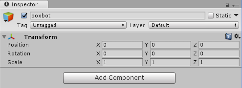
Before we start building the box robot, we’re going to create a parent game object to hold the articulation (if you’re new to Unity, click here to learn about game objects). Set the position of the container game object to be level with the ground. This will help us to place the feet starting on the ground. Leave the rotation and (0, 0, 0) and scale at (1, 1, 1). We’ll name this game object “boxbot” since this is where all of box robot’s body is going to be. A quick note before we begin: we will be building the box bot facing towards the front, and the “right” side will be the side of the box bot that is on the right when facing the box bot.
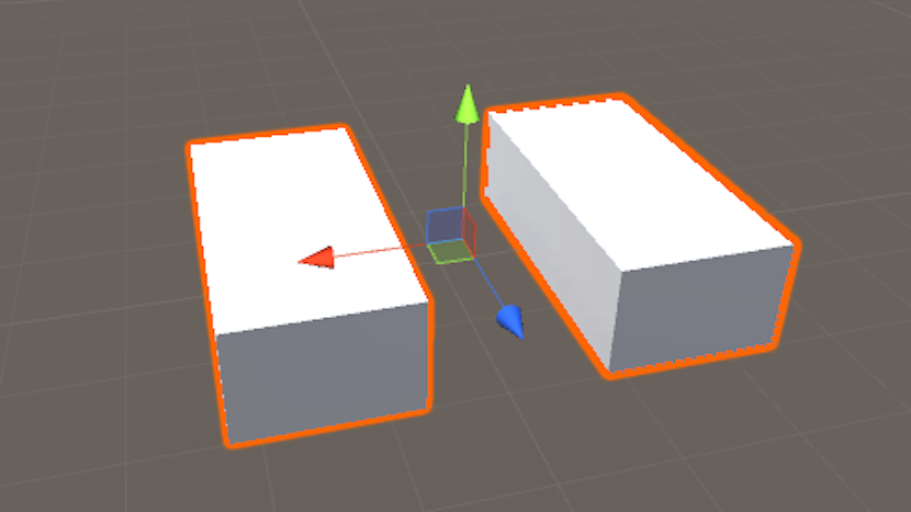
We’ll start off by creating the legs so that we know our box bot stands on the ground. Starting with main parts of the feet, create a 3D Object > Cube inside our parent articulation. Give this cube a scale of (0.15, 0.1, 0.3) and set it level with the ground. We’ll name this foot “rAnkle” and place it roughly 0.15 to the right of the center.
Now that the right foot is done, we’re going to duplicate the right foot to create the left foot. Move the new ankle of the left foot to the left, mirroring the position of the right foot. We will also rename these parts “lAnkle”, respectively.
The body parts of humanoids must follow a specific naming structure, which we will cover in the creation of each part. A summary of proper naming convention can be found in the glossary at the end of this tutorial.
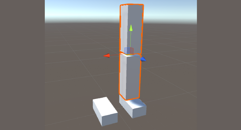
Now that we have both feet, we can start on the legs. Starting with the right calf, create a new cube for the lower right leg and rename it to “rKnee”. Scale it to (0.15, 0.45, 0.15) and place it above the right foot in the proper position. Be sure to leave a small gap between the top of the foot and the bottom of the lower leg. Moving up the leg, we have the thigh. To make it simple, duplicate the rKnee and move it up so that there’s a gap between the copy and the old rKnee. Rename this new block to “rHip” and maintain the same spacing between the two leg parts as with the leg and the ankle.
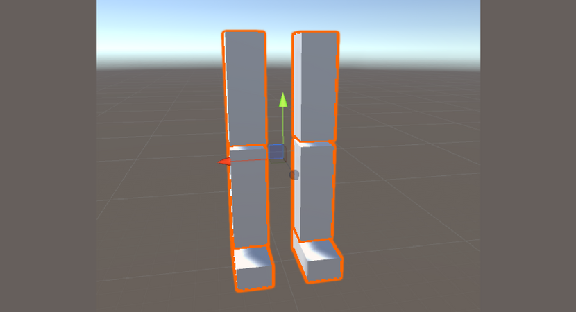
For the left leg, we’re going to use the same process that we did for making the left foot. Duplicate the right calf and thigh structure, and position it over the left foot, opposite the right leg. Rename the respective parts to “lKnee” and “lHip”.
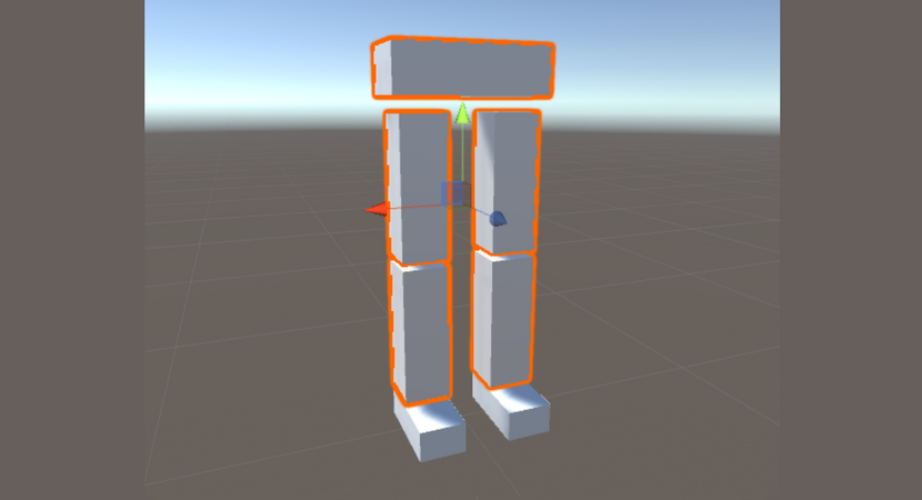
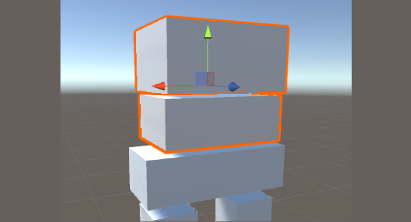
Create a new cube for the pelvis of the box bot and position it above the two legs, centering it. (This is why it’s helpful to build the legs around the local origin point of the container game object). Size the pelvis to (0.5, 0.15, 0.2) and name this game object “root”. This time we will keep a larger gap between the “root” and the legs than before.
Moving up the torso, create 2 cubes of roughly the same size and place them in a vertical stack above the root. These two do not have to have a specific naming convention, but you should name them something that makes sense, like “lowerBack” and “upperBack”, which we will be using in this case. We will be using a scale of (0.4, 0.15, 0.25) for the lowerBack and (0.4, 0.2, 0.3) for the upperBack. If you were using an additional back joint, you would want to scale down the height of each of the back pieces appropriately. While positioning the back joints, maintain the same gap between each part like how the legs were constructed.
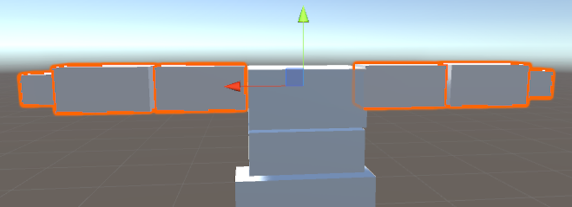
Next, we will create the arms of the box bot. Starting with the right arm, create two cubes for the upper arm and the forearms. For this box bot, we will use scale of (0.3, 0.15, 0.15) for each arm piece. Move the arms so they’re in-line with the top of the upper back part, and scale them along the horizontal axis to set the box bot in a “T” pose. Make sure the arms are in-line with each other so we have an upper arm and a forearm. Create another cube with a scale of (0.1, 0.1, 0.1) and move it to the end of the forearm piece. This component will be your box bot’s hand/wrist. Once again, maintain a small gap between each of the arm pieces and the “upperBack”. Do these same steps for the left arm. Name these components lShoulder/rShoulder, lElbow/rElbow, and lWrist/rWrist respectively.
Lastly, we have the head of the box bot. Create a cube with scale (0.3, 0.3, 0.3), and place it on top of the upper back in the center. We will name the cube head.
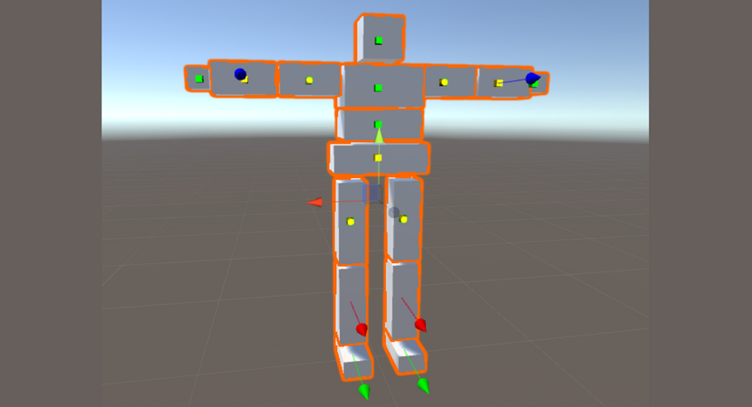
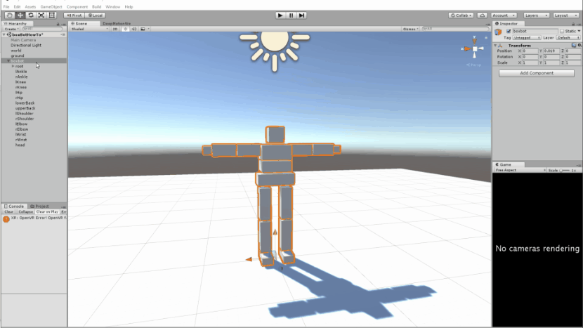
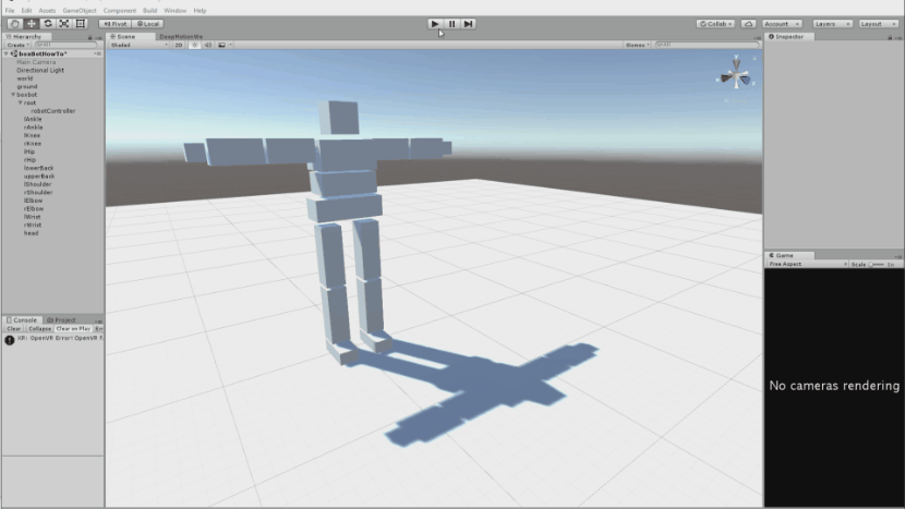
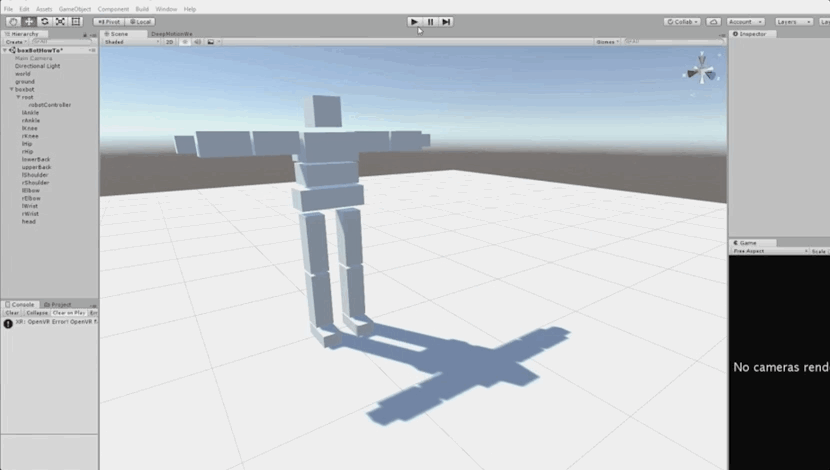
Your box bot should be made of 16 game objects total and look something like this:
Scales:
- Head: (0.2, 0.2, 0.2)
- Left and Right Shoulder: (0.3, 0.15, 0.15)
- Left and Right Elbow: (0.3, 0.15, 0.15)
- Left and Right Wrist: (0.1, 0.1, 0.1)
- Upper back: (0.4, 0.2, 0.3)
- Lower back: (0.4, 0.15, 0.25)
- Root (Pelvis): (0.5, 0.15, 0.2)
- Left and Right Hip: (0.15, 0.45, 0.15)
- Left and Right Knee: (0.15, 0.45, 0.15)
- Left and Right Ankle: (0.15, 0.1, 0.3)
Part 2: Adding Articulated Physics to Your Box Robot
Now that we have built the base structure, we need to add physically simulated Avatar joints (links) to each of the body parts. Refer to the following list to set up the Avatar components:
- Head: tntBallLink
- L/RShoulder: tntBallLink
- L/RElbow: tntHingeLink
- L/RWrist: tntBallLink
- UpperBack: tntBallLink
- Lower Back: tntBallLink
- Root: tntBase
- L/RHip: tntBallLink
- L/RKnee: tntHingeLink
- L/RAnkle: tntUniversalLink
Now that we have the Avatar components set up, go through and set the parents for each of the joints. Starting from the root (tntBase) and going down, set the root as the parent link for “l/rHip”, followed by “l/rHip” as the parent link for “l/rKnee”. The last joint to hook up for the legs is to set the “l/rKnee” as the parent link for “l/rAnkle”. Then we have to hook up the torso. Follow the same process of assigning the joint closest to the root as the parent for the next closest link, and so on. We have the “root” as the parent to “lowerBack, “lowerBack” as the parent to “upperBack”, and “upperBack” as the parent to “head”. For the arms we have “upperBack” as the parent to “l/rShoulder”, “l/rShoulder” as the parent to “l/rElbow”, and finally “l/rElbow as the parent to “l/rWrist”.
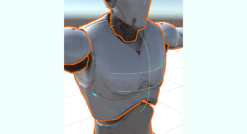
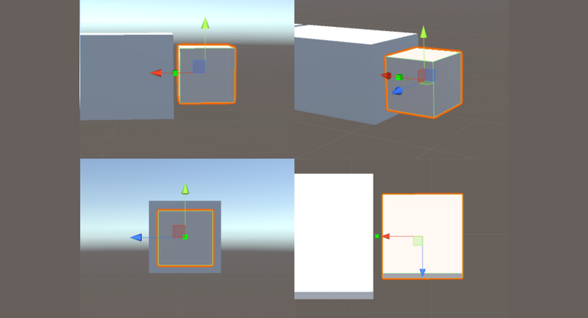
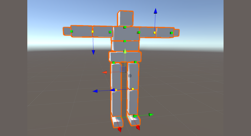
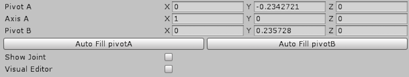
Now that every parent link is properly assigned, we can change the pivot points. To get the same look when highlighting the links as the picture above, scroll down to the bottom of the tntChildLink component and look at the PivotA/B section. Look for the “Show Joint” box below that and check it to have small yellow/green 3D shapes displayed, showing the pivot points. The shape will change depending on the link type. For links with a specific axis of motion, the shape will be a cylinder with a single arrow. The yellow shape is the PivotA (pivot point in parent link space), and the green shape is PivotB (pivot point in selected link space).
You want both of these points to line up or you will have some snapping as the engine forces the points to align. Alignment can be done in 3 ways: manually filling in the pivot fields, using the “Autofill PivotA/B” buttons, or by checking the “Visual Editor” box below the “Show Joint” box. When using 3D manipulator that appears over the yellow shape the two pivot points will automatically align. In this tutorial we will be using the manipulator to position the pivots. Go through each joint, checking the “Visual Editor” and “Show Joint” boxes. For each joint you’ll want to move the pivot to the previously created gap between the parent link and the current link, except for the shoulder. The shoulder pivot should be inside the shoulder collider. In general you’ll want to put the pivot in the center of the gap between the bones for a nicer visual.
How a pivot should be placed, using the wrist as an example:
How the pivot points will end up looking like for the entire box bot:
When changing the pivot for the hinge you’ll want to make sure to also adjust the axis so the joint rotates in the proper direction. In this case it will be easiest to fill out the fields instead of using the manipulator. Keep in mind that the AxisA variable is a unit vector, and the values will automatically adjust to keep it as such. I.e. if you wanted have the vector in the XY plane 45 degrees from the X axis, you could simply type (1, 1, 0), and it would automatically correct to (0.707.., 0.707.., 0).
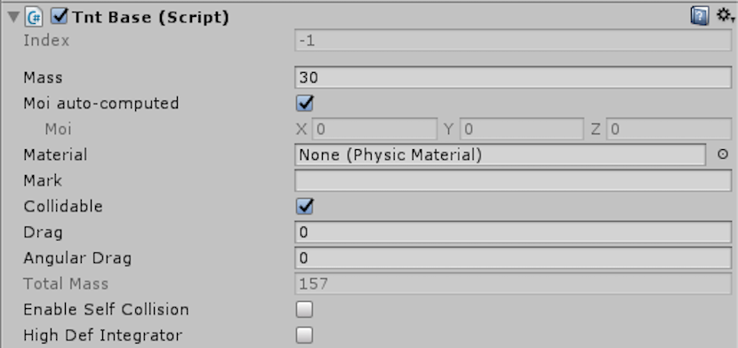
Before you can start running the box bot, you’ll need to give all of the bones (joints) a mass. We are going to use the following values:
- l/rAnkle: 10
- l/rKnee: 5
- l/rHip: 5
- root: 30
- lowerBack: 30
- upperBack: 30
- l/rShoulder: 5
- l/rElbow: 4
- l/rWrist: 2
- head: 5
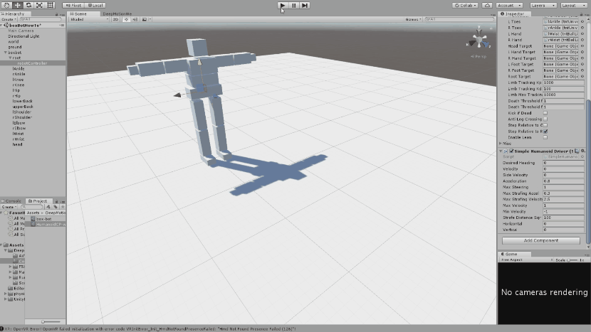
Now that you have finished setting up your articulation, you can run the scene and your character will drop the the ground like a ragdoll. Here is where you will want to make sure your character operates as expected when falling so any critical errors in design can be fixed. The next section will go over making your box bot move like a human.
Since we removed self-collision, the box bot will collapse onto itself.
Part 3: Humanoid Movement
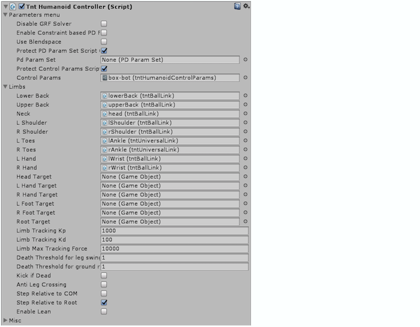
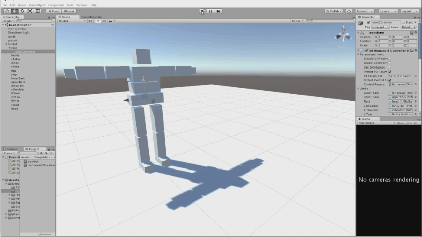
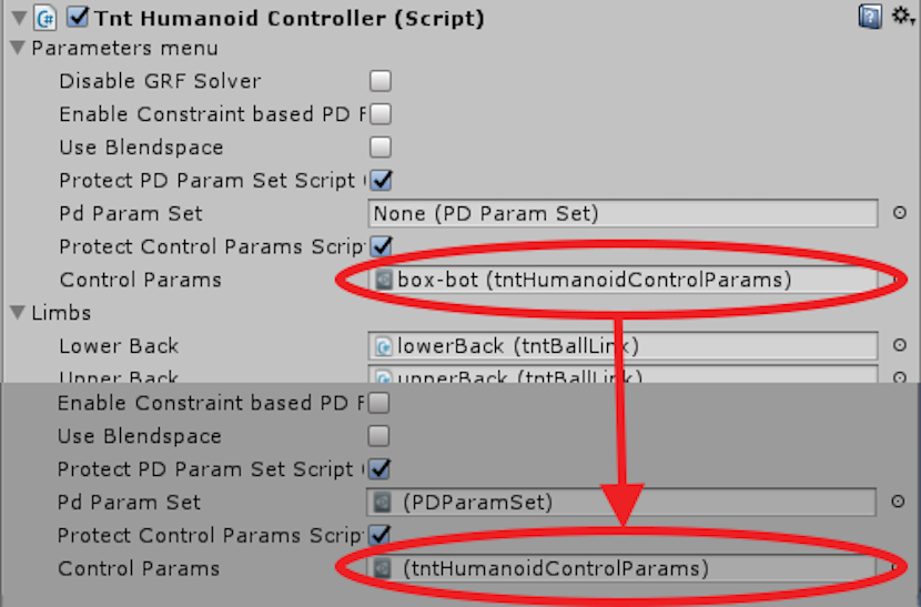
To give the box bot the ability to walk and balance, you’ll want to create a new empty game object under the “root” object, and attach a “tntHumanoidController” to it. Assign the limb fields for each body part. Duplicate the included “HumanoidCP-walker” control parameters, rename it, and assign that new control parameter object in the “Control Params” field.
In this game object we will also assign all of the appropriate limb fields so that the controller can easily find all of the limbs in this humanoid. For this demo we have the “Step Relative to Root” box checked as that produced the best balance, but you may want to try disabling both or having “Step Relative to COM” (center of mass) checked if you have balancing issues on your humanoid.
Next, we need to make sure the controller has the necessary muscle strength in the limbs to stand. The muscle strength of the joint for the controller is determined by the fields under the “Controller Pose Tracking Settings”. For now we only care about the Kp (muscle strength) and Kd (damping) fields. Too much Kp without enough or any Kd will result in very jerky movement that can cause chaotic behaviour. The following lists the values in a Kp/Kd format.
- L/RAnkle: 150/15
- L/RKnee: 0/0
- L/RHip: 500/20
- LowerBack: 300/30
- UpperBack: 200/20
- L/RShoulder: 100/10
- L/RElbow: 50/5
- L/RWrist: 20/2
- Head: 150/15
These values are not strict, but as a general rule you want the hips to be very strong as those are the central sources of your movement. The upper and lower backs need to be strong enough to support the weight of the arms, and the spine motion while walking will assist in balance. If the hips are too weak, the box bot will simply collapse. Test out the ability of your box bot to balance by running the scene. Another good test is to lift up the parent game object and let the box bot fall from a height and regain it’s balance.
The bot isn’t guaranteed to balance depending on your settings, but it will try!
Now that we know our box bot can balance on its own, we can move on to making it walk. Add the included “SimpleHumanoidController” to the same game object that the “tntHumanoidController” is attached to. This component will give you keyboard (WASD) control over your box bot.
While your character is starting to walk, you may notice that your box bot has a tendency to kick the back of it’s knee bones. If this is an issue, the fastest fix will be to disable self-collision in the tntBase script on the root game object. We can also partially fix this by modifying the values in the control parameters.
Now that we have our box bot doing a basic walk, we can have more control over the walk style and posture by modifying the values in the humanoid control parameters object. There are 107 parameters to choose from which do everything from changing the spine to how the ankle rotates throughout the stepping motion. If you run the scene while “Protect Control Params Script” is checked, you can experiment with these parameters live without making permanent modifications to the original. Simply double click on the temporary control params object created after the scene has started, and you can see the parameters affect the walk in real time.
You can find a more detailed explanation of the parameters in the documentation here, so for now we will just cover the few parameters that we will use to have our box bot walk with a bit of a swagger. We will be using the “spine twist” to emphasize each stride, and the “spine lean” to counterbalance the twisting. The “Spine Twist Offset and Body Frame Side Lean 1-6” is the amount of twist in the spine for 6 points in the complete walk cycle from beginning to end. We are also going to try raising the “Swing Foot Height 1 and 6” to prevent the robot from tripping on his own feet.
- Spine Twist Offset 1: 0.26
- Spine Twist Offset 2: 0.185
- Spine Twist Offset 3: 0.054
- Spine Twist Offset 4: -0.054
- Spine Twist Offset 5: -0.185
- Spine Twist Offset 6: -0.26
- Body Frame Side Lean 1: -0.192
- Body Frame Side Lean 2: -0.117
- Body Frame Side Lean 3: -0.027
- Body Frame Side Lean 4: 0.027
- Body Frame Side Lean 5: 0.117
- Body Frame Side Lean 6: 0.192
- Swing Foot Height 1: 0.1
- Swing Foot Height 6: 0.049
We can run the drop test using this controller as well.
You may notice that your robot is having trouble stumbling when it first starts walking. You can use the “Step Relative to COM/Root” to change how the box bot will make its steps. In this case we will be using “Step Relative to Root” to help fix the walking.
Proper Naming Conventions for Limbs of Avatar Humanoids
The following is a list of names used for each bone. Left and right directions are switched from what you expect due to the difference in coordinate handedness. Avatar uses OpenGL style coordinates (right-handed), but Unity uses left-handed coordinate axes. Naming corresponds to the joints that are simulated, which is not always perfectly aligned with the visual placement of the bone (for example, rWrist is a wrist joint that is attached to what visually appears to be the hand bone).
- head - The joint itself is located at the meeting point of the head and the neck
- upperBack - An alternative name is upperTorso.
- midBack - Not used in this tutorial, alternative name is midTorso.
- lowerBack - Alternate name is lowerTorso.
- lShoulder - The left shoulder. This bone is visually the upper arm.
- rShoulder - The right shoulder. This bone is visually the upper arms.
- lElbow - The left elbow. This bone is visually the forearm.
- rElbow - The right elbow. This bone is visually the forearm.
- lWrist - The left wrist. This bone is visually the hand.
- rWrist - The right wrist. This bone is visually the hand.
- root - This is named as such, because of where the root of the articulation is. An alternative name for this part is pelvis.
- lHip - The left hip. This bone is visually the thigh.
- rHip - The right hip. This bone is visually the thigh.
- lKnee - The left knee. This bone is visually the calf,.
- rKnee - The right knee. This bone is visually the calf.
- lAnkle - The left ankle. This bone is visually the foot.
- rAnkle - The right ankle. This bone is visually the foot.
Now you have all the tools to make a simple humanoid box robot! You can use this tutorial as a starting point to creating diverse physically simulated characters in Unity using DeepMotion Avatar. Apply today to try it for free! For a video version of this tutorial can be found here.
DeepMotion is working on core technology to transform traditional animation into intelligent simulation. Through articulated physics and machine learning, we help developers build lifelike, interactive, virtual characters and machinery. Many game industry veterans remember the days when NaturalMotion procedural animation used in Grand Theft Auto was a breakthrough from IK-based animation; we are using deep reinforcement learning to do even more than was possible before. We are creating cost-effective solutions beyond keyframe animation, motion capture, and inverse kinematics to build a next-gen motion intelligence for engineers working in VR, AR, robotics, machine learning, gaming, animation, and film. Interested in the future of interactive virtual actors? Learn more here or sign up for our newsletter.
DeepMotion's Articulated Physics Engine is a robotics level physics engine with robust joint simulation. This allows developers to simulate mechanical, industrial and robotic vehicles, passive ragdolls, as well as characters stable enough to self-balance as they navigate the digital world. ↩︎